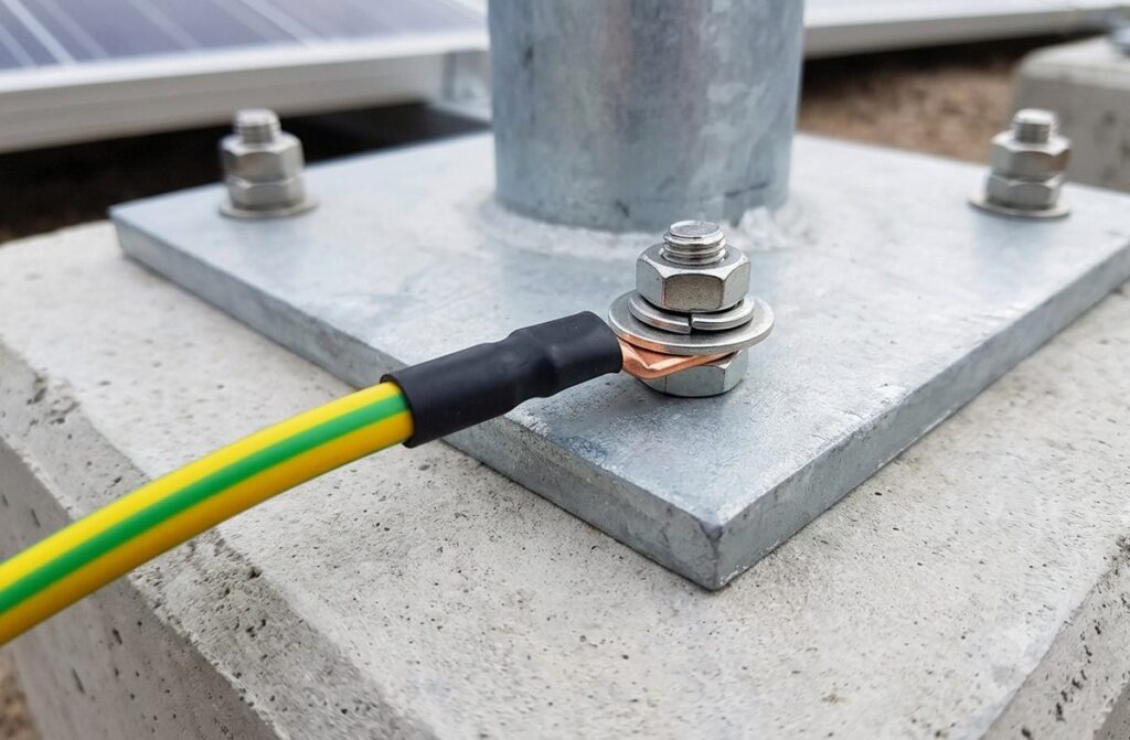
Earthing & Lightning Protection Guide – IS 3043 and IS/IEC 62305 Explained
By eNarayan Elex’s technical sales team – authorized Hex and OBO Bettermann earthing & lightning-protection distributor serving Hyderabad, Telangana and Andhra Pradesh. Last updated 21 August 2026.Earthing (grounding an electrical installation to limit fault voltage and protect equipment/people) and lightning protection (intercepting and safely conducting a direct lightning strike to earth) are two related but distinct systems, governed by two separate Indian standards: IS 3043, the Bureau of Indian Standards (BIS) Code of Practice for Earthing, and IS/IEC 62305, the (technically identical, IEC-aligned) standard for Protection Against Lightning, published in four parts. Every building needs earthing; not every building needs a dedicated lightning protection system – that is determined by a risk assessment, not by default.
eNarayan Elex stocks Hex earthing material and OBO Bettermann lightning-protection material under one roof in Hyderabad, so a site owner, electrician or facilities buyer can specify a compliant IS 3043 + IS/IEC 62305 system with one supplier. Below, we walk through both standards, how they differ, and which stocked products map to each.
Earthing vs Lightning Protection – Why They’re Not the Same Thing
It’s a common misconception on site that “earthing” and “lightning protection” are interchangeable. They are not:
Earthing (system + equipment earthing) is a permanent, always-active connection between electrical installations/enclosures and the general mass of earth, so that under a fault condition (insulation failure, short circuit) excess current has a low-impedance path to ground instead of flowing through people or damaging equipment. This is a requirement on every electrical installation, all the time.
Lightning protection is a separate system designed specifically to intercept a direct lightning strike (an air termination system – rods/mesh/conductors), safely carry that strike current down the structure (down-conductor system) and dissipate it into the ground (earth termination system) – usually its own dedicated earth electrode arrangement, bonded to the main earthing system.
A structure can have excellent electrical earthing and still be exposed to lightning risk if it has no dedicated air-termination/down-conductor system, and vice versa. eNarayan’s full earthing and lightning protection range covers both halves.
IS 3043 – Code of Practice for Earthing
IS 3043 is the Bureau of Indian Standards’ Code of Practice for Earthing (current edition: IS 3043:2018, Second Revision). It gives guidance on the methods used to earth an electrical system for the purpose of limiting the potential of current-carrying conductors and equipment relative to the general mass of earth. Its scope covers, among other things:
System earthing and equipment (non-system) earthing for LT and HT installations
Earthing in potentially hazardous areas, and for street lighting and other supply installations
Calculation of earth-fault currents and measurement of earth-electrode/loop resistance
Earthing requirements for data-processing/sensitive electronic equipment
Earth Electrode Types Compared – Plate, Pipe/Rod and Chemical
IS 3043 recognises several electrode constructions, and the right choice for a given site depends on soil conditions, available space, and how deep a stable low-resistivity soil layer sits – not on a single “best” electrode type.
Electrode type
Typical construction
Where it’s used
Practical notes
Plate electrode
GI plate (commonly around 60 x 60 cm, ~6 mm thick) or copper plate (commonly around 60 x 60 cm, ~3.15 mm thick), buried vertically in a pit, typically several metres deep
Sites where a rod cannot be driven deep – shallow rock, very high water table, or where a large surface-area electrode is specifically wanted
Gives good surface area without needing depth; labour- and material-heavy to install and harder to test/maintain than a rod, so increasingly reserved for the specific cases a rod can’t handle rather than used as a default
Pipe / rod electrode
GI or copper-bonded pipe/rod driven vertically into the ground; copper-bonded rods can be coupled to reach greater depth
The default choice for most new electrical earthing installations
Copper-bonded rod reaches deeper, more stable, lower-resistivity soil layers than a shallow plate; couples easily for depth; lighter to handle and install; grids well with strip conductor for substations, solar and larger installations
Strip / conductor electrode
Buried horizontal strip or conductor, sometimes combined with rods in a grid
Substations, larger industrial sites, and installations needing a low-resistance grid rather than a single point electrode
Used to interconnect multiple rod electrodes into a mesh/grid, lowering overall system resistance beyond what a single electrode can achieve
Chemical earthing electrode
A backfill compound (conductive, moisture-retentive) placed around a pipe/rod electrode
High-resistivity soil (rocky, sandy, very dry) where a plain rod or pipe alone can’t reach an acceptable resistance value
Chemical/compound treatment lowers the effective resistance of the electrode-to-soil interface and helps maintain performance through dry seasons; a genuinely site-specific decision driven by the soil resistivity reading, not a default upgrade
Why Soil Resistivity Drives the Design
The resistance an earth electrode achieves depends primarily on soil resistivity at the site, moisture content, and the electrode’s type, size and depth – which is why IS 3043 gives calculation methods for multiple electrode types rather than a single fixed answer. The correct design sequence is:
Measure soil resistivity at the actual site (a proper resistivity test, not an assumption based on a nearby site or general soil type).
Calculate the expected single-electrode resistance for the candidate electrode type/size/depth against that measured resistivity.
Determine how many electrodes (and whether a grid/strip interconnection) are needed in parallel to reach the target design resistance for the installation.
Where resistivity is high (rocky or very dry soil), consider chemical/backfill compound treatment or additional electrodes rather than accepting a compromised resistance value.
In practice this means the correct number, type and spacing of earth electrodes for a given site is a site-specific design exercise, not a fixed catalogue number applied everywhere.
IS/IEC 62305 – Protection Against Lightning
India has adopted the IEC 62305 lightning-protection standard as IS/IEC 62305, in four parts, technically identical to the international IEC standard:
Part
Title
Covers
Part 1
General Principles
Fundamentals of the lightning phenomenon and protection concepts
Part 2
Risk Management
Risk assessment methodology – decides whether a lightning protection system is needed, and to what protection level
Part 3
Physical Damage to Structures and Life Hazard
Design of the air-termination, down-conductor and earth-termination systems; touch/step-voltage protection
Part 4
Electrical and Electronic Systems Within Structures
Surge protection (SPDs) and bonding for internal electrical/electronic systems
Lightning Protection Levels (LPL I-IV) Explained
IS/IEC 62305 defines four Lightning Protection Levels, each corresponding to a different design interception efficiency and reference lightning current. The level required for a given structure is an OUTPUT of the Part 2 risk assessment, not something chosen upfront.
LPL
Design intent
Typical application
LPL I
Highest protection level; intended to intercept the great majority of lightning flashes for the most critical/high-risk structures
Hospitals, high-hazard industrial sites, structures where consequences of a strike are most severe
Multi-family residential buildings, standard industrial and commercial buildings
LPL IV
Basic protection level
Lower-risk structures where the risk assessment indicates minimal exposure
Each LPL also corresponds to specific design parameters in Part 3 (rolling sphere radius, mesh size, and typical distance between down-conductors) that get tighter as the protection level rises from IV to I – a higher protection level is designed to intercept a wider range of strike severities including smaller, more easily-missed strikes. The exact numeric parameters for each LPL are specified in Part 3 and should be taken from the current edition of the standard at design time rather than assumed.
Why Part 2 (Risk Assessment) Comes First
A lightning protection system is not a blanket requirement on every building – IS/IEC 62305 Part 2 defines a risk-assessment method (based on the structure’s location, height, occupancy, lightning-strike frequency for the region, and the value of what’s being protected) that determines whether protection is warranted and, if so, which LPL the design should target. This is why a proper lightning-protection quote should always start with – or at least reference – a risk assessment rather than jumping straight to “install an air terminal and down-conductor.”
The risk assessment weighs several loss categories – risk to human life, risk of loss of service to the public, risk of cultural heritage loss, and risk of economic loss – against the acceptable/tolerable risk threshold for that category, and the output determines both whether protection is needed and at what LPL.
External vs Internal Protection (Part 3 and Part 4)
External LPS (Part 3): the visible system – air-termination rods/mesh/conductors to intercept the strike, down-conductors to carry the current to ground, and a dedicated earth-termination system, plus separation-distance rules so the strike current doesn’t jump across to other services.
Internal LPS (Part 4): equipotential bonding of metallic services entering the structure, and surge protection devices (SPDs) staged at the incoming supply and at sensitive downstream equipment, to stop induced surges from damaging electrical/electronic systems even when the direct strike itself is safely conducted to earth externally.
Both halves are needed for complete protection – external-only protection can still let a damaging surge into a building’s wiring and electronics via induction, which is exactly what Part 4’s SPD/bonding requirements address.
Maintenance and Testing Schedule – What Should Be Checked, and How Often
Earthing and lightning protection systems degrade over time – corrosion at electrode connections, soil resistivity changes seasonally, and mechanical connections loosen. A system designed correctly but never re-tested can quietly drift out of compliance. General good-practice intervals (always confirm the specific interval required for your installation type/occupancy against the applicable standard and any site-specific/statutory requirement):
Visual inspection of accessible earthing/LPS components (bonding connections, electrode heads, down-conductor test links, corrosion at joints): periodic visual checks as part of routine electrical maintenance, more frequently in exposed/corrosive environments (coastal, industrial, high-pollution areas).
Earth electrode/loop resistance measurement: periodic testing (commonly on an annual cycle for many installations, though the correct interval depends on soil type, installation criticality, and any site-specific code requirement) to confirm the electrode system still meets its design resistance target.
Continuity testing of the full earthing/bonding network: to confirm no connection has corroded, loosened, or been disturbed by other site work (excavation, renovation) since the last test.
Lightning protection system inspection: visual inspection of air-termination rods/mesh, down-conductors and their test links/joints, plus continuity and earth-resistance testing of the LPS earth-termination system, on a periodic cycle appropriate to the structure’s risk category.
SPD condition check: Surge Protective Devices have a finite service life and most incorporate a visual status indicator (or remote signalling contact) showing whether the SPD has degraded from surge events and needs replacement.
Post-event inspection: after any known significant lightning strike near the structure, or after major site excavation/construction work near buried electrodes, an out-of-cycle inspection is good practice.
Exact statutory testing intervals vary by occupancy type, industry, and local regulatory requirement – a qualified electrical/LPS contractor should confirm the applicable interval for a specific site rather than relying on a generic maintenance calendar.
Hex vs OBO Bettermann – Product Mapping to the Standards
eNarayan Elex carries earthing and lightning-protection material from Hex and OBO Bettermann. Broadly, the two brands map onto the IS 3043 / IS/IEC 62305 split as follows – exact model-level specification and availability should be confirmed against current stock at order time:
Requirement (per standard)
Product category
Brand coverage at eNarayan
IS 3043 – earth electrodes
GI/copper pipe and rod electrodes, plate electrodes, earthing strip, chemical/compound backfill electrodes, earthing accessories (clamps, connectors, inspection chambers)
For a specific project, share the structure type, location, height and any existing electrical earthing details via our contact page, and the right product mix across both brands can be confirmed against current stock. See the full earthing and lightning protection catalogue for what’s stocked today. SPDs are usually mounted inside the main distribution panel — our Control Panel Accessories Buyer’s Checklist covers the rest of what that panel needs. Protecting sensitive equipment from outages as well as surges? See our Numeric UPS VA Rating Sizing Guide for backup-power sizing.
Practical Checklist for a Site Owner or Consultant
Has electrical (system + equipment) earthing been designed per IS 3043, with electrode type/count based on an actual soil-resistivity reading for the site – not assumed?
Has the electrode type (plate, pipe/rod, strip/grid, or chemical) been chosen against the site’s measured soil resistivity and space constraints, rather than defaulted?
Has a lightning risk assessment been carried out per IS/IEC 62305 Part 2 to confirm whether a dedicated LPS is required, and at what protection level (LPL I-IV)?
If an LPS is required: is the external system (air termination + down-conductors + dedicated earth termination) specified per Part 3 at the correct LPL?
Is the earth-termination system for the LPS bonded to the main electrical earth, as required for equipotential bonding?
Has surge protection (SPDs) and internal bonding per Part 4 been specified for incoming supply and sensitive equipment – not just the external strike path?
Is a periodic testing/maintenance schedule in place for earth-resistance measurement, LPS continuity, and SPD condition checks – not just a one-time commissioning test?
Has an out-of-cycle inspection been scheduled after any known significant strike event or major excavation/construction near buried electrodes?
Frequently Asked Questions
1. What’s the difference between earthing and lightning protection?
Earthing is a permanent electrical-safety system that gives fault current a safe path to ground during everyday operation. Lightning protection is a separate system specifically designed to intercept and safely conduct a direct lightning strike; the two systems are bonded together but serve different purposes.
2. Which Indian standard governs earthing design?
IS 3043, the Code of Practice for Earthing (current edition IS 3043:2018), covers system and equipment earthing design, electrode calculation methods, and earthing for hazardous areas and sensitive equipment.
3. Which standard governs lightning protection in India?
IS/IEC 62305, published in four parts (General Principles, Risk Management, Physical Damage to Structures, and Electrical/Electronic Systems), technically identical to the international IEC 62305 standard.
4. Does every building need a lightning protection system?
No. IS/IEC 62305 Part 2 defines a risk-assessment method based on the structure’s location, height, occupancy and regional lightning-strike frequency to determine whether a dedicated system is warranted, and at what protection level (LPL I-IV) – it is not a blanket requirement.
5. What determines how many earth electrodes a site needs?
Primarily the soil resistivity at that specific site, along with the electrode type, size and depth used. High-resistivity (rocky/dry) sites often need chemical/backfill-treated electrodes or a larger electrode grid to reach the same target resistance a low-resistivity site achieves with fewer electrodes.
6. What is an SPD and why does lightning protection need one?
A Surge Protective Device (SPD) limits transient overvoltages (surges) that can be induced into a building’s electrical/electronic systems even when a direct lightning strike is safely conducted to earth externally – this is the Part 4 “internal protection” half of a complete IS/IEC 62305 design. SPDs have a finite service life and most show a visual status indicator that should be checked periodically.
7. What earthing/lightning protection brands does eNarayan Elex stock?
eNarayan Elex, Rasoolpura, Hyderabad, stocks Hex earthing material and OBO Bettermann lightning-protection material, covering electrode/accessory components for IS 3043 earthing and air-termination/bonding/SPD components for IS/IEC 62305 lightning protection.
8. Can existing electrical earthing be reused for a new lightning protection system?
The lightning-protection earth-termination system should be bonded to the main electrical earth for equipotential bonding, but its own electrode design and resistance target are assessed separately as part of the IS/IEC 62305 design – confirm with a qualified designer rather than assuming the existing electrical earth alone is sufficient.
9. What’s the difference between a plate electrode and a pipe/rod electrode?
A plate electrode is a buried flat metal plate offering surface area without needing much depth – useful where a rod can’t be driven (shallow rock, high water table). A pipe/rod electrode is driven vertically and can reach deeper, more stable low-resistivity soil, is easier to install and test, and is generally the default choice for new work unless site conditions specifically favour a plate.
10. How often should earthing and lightning protection systems be tested?
General good practice is periodic visual inspection plus earth-resistance/continuity measurement on a recurring cycle (commonly annual for many installations, though this varies by soil type, occupancy and site-specific requirement), with SPD condition checks as part of the same routine and an out-of-cycle inspection after any known significant strike or major nearby excavation. The exact statutory interval for a specific occupancy type should be confirmed with a qualified electrical/LPS contractor.